|
|
|
Pressure Recover System
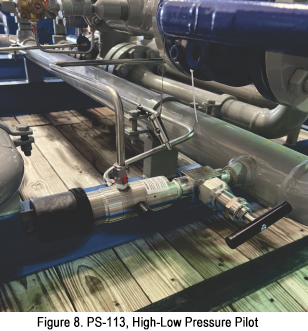
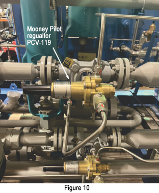
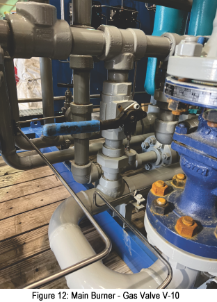
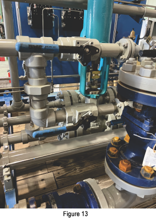
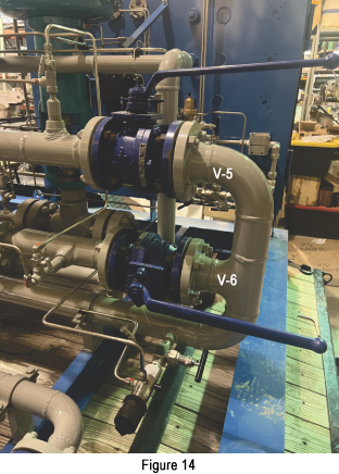
Operating PRS Purge PRS, Set PCV's & Mooney Reg Pressures, Cut #1, Cut #2 and Final Discharge 1. Ensure AMOT ESD valve on control panel is reset and in active operating mode by lifting tab until it holds in place. See Figure 1. 2. Identify V-3, V-4, V-5, V-6 valves in front and back of the Mooney Regulator on Cut 3. Close all 4 valves. 3. Cut #1: Slowly set PCV-104 from 0 to 1,800 psig using the 0 - 5000 psig dial on control panel controller. It is recommended to set PCV-104 between 1,700 and 1,800 psig. CAUTION: the downstream PSV is set for 2,100 psig. 4. Cut #2: Slowly set PCV-108 from 0 to 800 psig using the 0 – 1000 dial on the control panel controller. It is recommended to set PCV-108 between 700 and 800 psig. CAUTION: the downstream PSV is set for 1,000 psig. 5. Final Discharge: Slowly open V-3 or V-4 (Figure 13) and supply pressure to the Mooney Regulator. Set the final cut Mooney regulators to desired delivery pressure range using the pilot regulator in Fig. 10, from 50 to 250 psig. Slowly open V-5 or V-6 (Figure 14) to load to the final discharge valve. Repeat for the second Mooney regulator if needed. CAUTION: the downstream PSV is set for 300 psig. CAUTION: All high pressure PSV's are directed towards the rear of the PRS. Use caution when standing or working at rear of PRS. 6. Open final discharge valve (Figure 11) to fill the hose up to the customer connection valve. 7. If discharge pressure is desired above 285 psi use the 2nd cut customer discharge valve. 8. Purge gas for 10 to 15 seconds through PRS to purge valve located at customer supply point. 9. Open V-10 (Figure 12) Main Burner gas supply valve and close V-66 (Figure 3) needle valve used for startup gas. See Figure 12 & Figure 3. This should satisfy the AMOT ESD valve. 10. Commence flowing gas to customer supply point. 11. Monitor and record flowing pressures and temperatures. 12. Pushing the AMOT ESD button will drop control pressure from the ESD loop and the PCV-104 (Cut 1) and PCV 108 (Cut 2) will close and stop flow. To reset the system, Identify the problem then go to Step 1 of Operating PRS. NOTE: Pressure sensor PS-113 downstream of the Mooney regulators is set for 40 psig and must be satisfied by the AMOT ESD Valve in order to allow flow. This pressure shut down can be adjusted to another desired setting. See Figure 8. NOTE: Temperature sensor TS-114 is set for 32F (0C) and must be satisfied by the AMOT switch in order to allow flow. This temperature shut down can be adjusted to another desired setting. See Figure 7. This valve is used to protect the system from too cold of gas flow. This is a control regulator, turning in increases the set pressure and turning out decreases the set pressure. This pressure MUST be lower than your flowing pressure. De-pressure PRS & Demobilize Equipment 1. Close all tube valves on tube trailer. 2. Close customer supply valve. 3. De-pressure high pressure hose connected to Inlet #1 (or Inlet #2) to 0 psig by opening blowdown needle valve behind control panel. Blowdown tubes are mounted behind the control panel and are pointed horizontally away from the panel. See Figure 3. 4. De-pressure low pressure supply lines to 0 psig through customer purge valve at supply point. 5. Blowdown fuel gas scrubber using bottom valve on scrubber vessel. 6. Ensure all pressure gauges on control panel read 0 psig. See Figure 1. 7. Ensure both high pressure and low pressure supply hoses are limp before disconnecting. 8. Set PCV-104 and PCV-108 dials to 0 psig and close PCV controller doors. 9. Disconnect high pressure hose from tube trailer & control panel, close and secure control panel doors. 10. Disconnect low pressure supply hose from PRS & customer delivery point and rig out grounding cables. 11. Lower and secure latch on smokestack. CAUTION: Smokestack will be hot to the touch. Allow to cool before lowering & installing bolts. 12. Securely fasten flame arrestor cover on heater once face of flame arrestor has cooled. 13. Demobilize equipment from customer site. 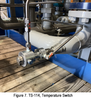
TGT PRS Manual Page 4 |
| |
|
Tulsa Gas Technologies 4809 S. 101st E. Ave. Tulsa, OK 74146 (918) 665-2641
|